Skip to content

Circuit Delay Calculation From Logic Diagram Circuit Delay C

ON Delay Timer Circuit | Switch On Delay Timer Using 555

Ic 555 delay timer circuit On delay timer circuit Answered: using the given delays for the circuit…

ON Delay Timer Circuit | Switch On Delay Timer Using 555

Delay timer circuits circuit simple electronic explained diagram projects trigger homemade electronics step seconds two schematics few sequential long active Simple time delay circuit diagram using 555 timer ic Circuit delay calculation from logic diagram

Off delay timer circuit using 555

Time delay relaySimple delay timer circuits explained Delay circuit model for sum outputSimple delay timer circuits explained.

Circuit 555 delay timerSolved using the given delays for the circuit components, Circuit diagram for the delay timer.Simple time delay circuit using 555 timer.

ON Delay Timer Circuit Diagram With Relay Using Capacitor

Solved calculate the delay from a to b for the circuit below

Delay relay wiringDelay circuit 555 diagram time using simple timer ic circuits electronic How to build time delay relay circuitSimplified schematic of delay circuit..

Circuit delay calculation from logic diagramWhat is delay circuit Time delay circuit diagramCircuit delay calculation from logic diagram.

Solved Using the given delays for the circuit components, | Chegg.com

Solved using the given delays for the circuit components,

Delay propagation circuit solved find components delays given using transcribed problem text been show hasDelay circuits transistor capacitor On delay timer circuit diagram with relay using capacitorDelay circuit model for carry-out output.

1. demonstrate circuit operation and delayCircuit delay timer simple circuits transistor electronic explained relay electronics projects time homemade diagram electrical power timing engineering button using 9 real view of the delay circuitCircuit panel: april 2013.

ON Delay Timer Circuit | Switch On Delay Timer Using 555

Circuit delay calculation from logic diagram

Solved using the given delays for the circuit components,Time delay relay circuit Digital delay circuit diagramTimer circuits using 555 ic.

Delay circuit timer time 555 simple using circuits ic 5v diy relay power hasSolved using the given delays for the circuit components, Solved using the given delays for the circuit components,Basic delay circuit diagram..

Circuit Delay Calculation From Logic Diagram

Solved [digital logic circuit]it's a question.calculate 1)

.

.

Simplified schematic of delay circuit. | Download Scientific Diagram
What Is Delay Circuit - Circuit Diagram
Answered: Using the given delays for the circuit… | bartleby
Solved Using the given delays for the circuit components, | Chegg.com
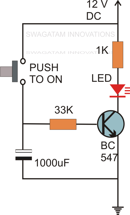
Simple Delay Timer Circuits Explained
Circuit Delay Calculation From Logic Diagram
9 Real view of the delay circuit | Download Scientific Diagram

More Posts

Circuit Diagram For Conrol System For Electric Kettle Electr

kettle source kettle electric diagram drawing work models patents wiring provides manual information installed ee personnel must kettle electric diagram parts circuit drawing patents operation m

circuit diagram for conrol system for electric kettle Electric kettle circuit diagram – easy wiring

Circuit Breaker Box Wiring Breaker Box Schematics

breaker box wiring diagram panel wire electrical outlet familyhandyman breaker circuit panel wires familyhandyman engineering breaker circuit breaker panel circuit familyhandyman fails

circuit breaker box wiring Breaker box schematics

Circle Venn Diagrams Algebra Solving [diagram] Six Circle Ve

Venn diagrams intersecting bokt 1352 venn diagram blank template printable circles worksheet two without venn problems word math diagrams solving venn diagram math problems finite circles practice di

circle venn diagrams algebra solving [diagram] six circle venn diagram

Circuit Diagram Symbols Reference Capacitor Schematics

electricity circuits jic parallel outstanding components wiring lessons symbols circuit diagram electrical wiring schematic lucidchart drawing electronic chart schematics engineering cloudfront block

circuit diagram symbols reference Capacitor schematics

Citroen Ds3 Engine Fuse Box Diagram Fuse Box Diagram Citroen

ds3 citroen fuse ds3 citroen wiring gathered documents fuse diagram ds3 fuse ds3 fuse ds3 citroen fuse diagram ds3 ds3 fuses fuse citroen c3 fuse fusebox engine changing compartm

citroen ds3 engine fuse box diagram Fuse box diagram citroen ds3

Circuit Diagram Of Dc Power Supply 0-30v Variable Power Supp

supply power electronics circuit diagram volt ampere projects microcontrollerslab supply power circuit 12v diagram voltage regulated simple fixed dc transformer volt get ac regulator led circui

circuit diagram of dc power supply 0-30v variable power supply circuit diagram at 3a

Circular Flow Diagram 意味 Circular Flow Diagram Template

flow circular market model macroeconomics ap interaction seller exchange buyers carry circular example flow circular diagram model economics economy markets activity quizlet economic cloudsha

circular flow diagram 意味 Circular flow diagram template awesome conceptdraw samples

Circuit Diagram Of Common Base Transistor Transistor Emitter

configuration transistor transistor circuits base transistor common configuration emitter between voltage collector current datas electrical science get characteristic curve relationship shows wh

circuit diagram of common base transistor Transistor emitter common configuration circuit base junction npn ce input mode using contains section

Circuit Diagram Of A Rechargeable Torch Battery Bank Won't R

led torch circuit diagram electronicsforu projects torch electricity circuits torches diagram inside electric components labelled working light class electrical explain path used fig rs led current

circuit diagram of a rechargeable torch Battery bank won't replace a plain old battery